Examples of Result Simulated with Finite Element Method (Part.2)

Examples of Result Simulated with Finite Element Method (Part.2)

 Japanese
|
All Rights Reserved by Dr. SHINOZUKA Jun.
|
Orthogonal and steady state cutting mechanism can simulate with thermo elastic plastic FEM with Iterative Convergence Method(ICM). Using this method we can know cutting forces, cutting temperature, shear angle, stress and temperature distribution on tool face, etc. In this simulation, a flow stress characteristic model that depends on strain, strain rate, temperature and history of them was considerd to simulate cutting mechanism accurately.

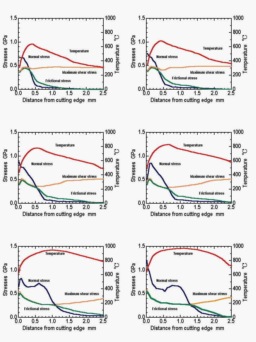
The influence of the first rake angle upon the cutting mechanism. Tools are flat rake face tools.
Dark bkue line indicates the normal stress on the rake face, dark green line indicates the frictional stress, orange line indicates the maximum shear stress on the chip, red line indicates the temperature. From the orange line, you will can see that the yield stress on the chip endure material hardning and thermal softning. Accordingly the frictional stress is changing.

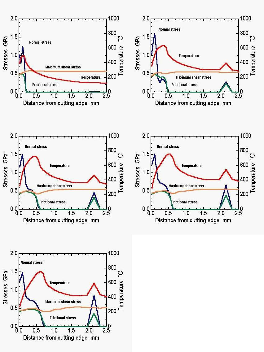
The influence of the cutting conditions ( undeformed chip thickness ) upon the cutting mechanism. Tools are grooved rake face tools.
Dark bkue line indicates the normal stress on the rake face, dark green line indicates the frictional stress, orange line indicates the maximum shear stress on the chip, red line indicates the temperature. From the orange line, you will can see that the yield stress on the chip endure material hardning and thermal softning. Accordingly the frictional stress is changing.
There are two portions where the stresses act on, around the cutting edge and chip breaker point.