SHINOZUKA Jun Ph.D.

Associate Professor,
Department of Mechanical Engineering
Yokohama National University, Japan

This page has opened to public since April 14 2008.

Last update March 18 2023
SHINOZUKA Jun Ph.D.
Associate Professor,
Department of Mechanical Engineering
Yokohama National University, Japan
This page has opened to public since April 14 2008.
Last update March 18 2023
 Japanese
|
All Rights Reserved by SHINOZUKA Jun.
|
Get a step ahead toward your dream
Fire walk with me
Research interests are the clarification of cutting phenomena and the creation of next generation machining system.
EXPERIMENTS CONCERNING MACHINING
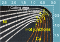
This page shows the measurement of the temperature distribution at the tool-chip interface with minute thermocouples fabricated on the tool face. In addition to the introduction of the previous works I done, the latest work, which seven pairs of micro Cu/Ni thermocouples are set on the rake face near the cutting edge, is introduced.
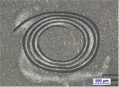
A sandwich tool that hard materials and soft materials are laminated has been proposed for fabricating micro grooves by ultrasonic machining. By employing this method, we can fabricate an intelligent tool with built-in micro sensors.
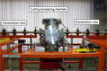
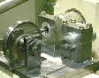
High-speed and ultra high-speed cutting tester have been developed to investigate cutting phenomena. The testers are airgun type; cutting tool or workpiece is accelerated by compressed air. Cutting speed 150 m/s can be achieved in atomosphere condition so far. The tester have been improved to achieve much faster cutting speed.
DYNAMIC FEM SIMULATION
Two dimensional Impact and orthogonal cutting processes in unsteady state and ultra high-speed cutting
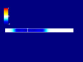
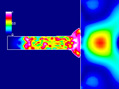
This page shows FEM(finite element method) simulations of propagation of an elastic stress wave by using FEM simulator that I have developed. The FE analysis is based on a dynamic and thermo elastic plastic finite element method. The programing language of the core of FEA is Fortran and that of a drawing software of the results is Microsoft Visual C#.NET. I have also developed the drawing software.
This page shows FEM(finite element method) simulations of propagation of elastic plastic stress waves by using FEM simulator that I have developed. The FE analysis is based on a dynamic and thermo elastic plastic finite element method. The programing language of the core of FEA is Fortran and that of a drawing software of the results is Microsoft Visual C#.NET. I have also developed the drawing software.
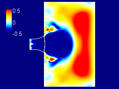
This page shows FEM(finite element method) simulations of spalling phenomenon by using FEM simulator that I have developed. The FE analysis is based on a dynamic and thermo elastic plastic finite element method. The programing language of the core of FEA is Fortran and that of a drawing software of the results is Microsoft Visual C#.NET. I have also developed the drawing software.
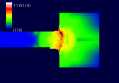
This page shows FEM(finite element method) simulations of ultra high-speed impact by using FEM simulator that I have developed. The FE analysis is based on a dynamic and thermo elastic plastic finite element method. The programing language of the core of FEA is Fortran and that of a drawing software of the results is Microsoft Visual C#.NET. I have also developed the drawing software.
This page shows FEM(finite element method) simulations of various type of ultra high-speed impact by using FEM simulator that I have developed. The FE analysis is based on a dynamic and thermo elastic plastic finite element method. The programing language of the core of FEA is Fortran and that of a drawing software of the results is Microsoft Visual C#.NET. I have also developed the drawing software.
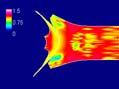
This page shows FEM(finite element method) simulations for metal cutting processes in unsteady state by using dynamic FEM cutting simulator that I have developed. The FE analysis is based on a dynamic and thermo elastic plastic finite element method. The programing language of the core of FEA is Fortran and that of a drawing software of the results is Microsoft Visual C#.NET. I have also developed the drawing software.
This page shows FEM(finite element method) simulations for metal cutting processes in ultra high-speed cutting by using dynamic FEM cutting simulator that I have developed. The FE analysis is based on a dynamic and thermo elastic plastic finite element method. The programing language of the core of FEA is Fortran and that of a drawing software of the results is Microsoft Visual C#.NET. I have also developed the drawing software.
STATIC METAL CUTTING MECHANICS
Orthogonal metal cutting FEM simulation, Chip Breaking process FEM simulation
 Formulation of Finite Element Method
Examples of Finite Element Method Simulations
( You can see Animation GIF files )
The programing language of FEM was Fortran 77, and simulations were done using EWS (HP9000 model712 715). Graphic program code as the result viewer are written with Visual C#.NET.


These results are obtained from Thermo-Elastic-Plastic Finite Element Method with Iterative Convergent Method. From these results, we can know easily the cutting performances such as cutting forces, chip shape, the distributions of temperature and stresses on the rake face, and also we can easily evaluate the quality of the machined products. The influences of these cutting performance upon the cutting conditions, material conditions and tool rake face geometry are predicted.
These results are obtained from Thermo-Elastic-Plastic Finite Element Method. From these results, we can know easily whether chip breaks or not, in short, chip breakability. In order to design high performance metal cutting tool, we have to investigate the chip breakability. But it may be impossible in actually to make a lot of types of tool tips and to test them. Numerical simulation such this FEM is very usufull.
This engine is very very gentle to the earth environment. There is no exhaust gas. If temperature gradient can be made, everything can be used for the energy source. That is, the sun energy, terrestrial heat energy, and oceanic energy, etc. can be used.