Cutting Temperature Simulator
employing
a Finite Difference Method
This software is written by Microsoft Visual Basic (ver.6.0 SP.6). at 2017 June 17
N88BASIC version by Dr. Obikawa, Toshiyuki.
Microsoft Quick Basic version
by Dr. Sasahara, Hiroyuki and Dr. Obikawa, Toshiyuki.
Microsoft Visual Basic version by
Dr. Shinozuka, Jun and Dr. Obikawa, Toshiyuki.(1997-)
This page has opened since 1998.

 Japanese version
|
All right reserved by Professor Obikawa, Toshiyuki (previous: The University of Tokyo, current: Tokyo Denki Universuty).
Featuring Dr. Shinozuka, Jun.
Unauthorized duplication shall be a violation of applicable laws.
|
The most superior point of this software is to be able to
get the knowledge easily the temperature durling metal cutting processes.
The cutting temparature is one of the very important factores
for hight efficient machinning.
Because the tool wear or tool fracture depend strongly on the temperature.
But it is very difficult to know the temperature distribution by
experimental methods.
Accordingly the numerical simulation is very effective.
This software runs on Windows 95, source code is written by Visual Basic.
The calclulation time is very short.
It takes about one minute ( CPU ; Pentiun 130 MHz, Memory ; EDO-32MB).
This software will help you on the cases as follows;
Before you try to develop the newly cutting conditions or cutting tool.
You want to try to study how to calculate the temperature
by Finite Difference Method.
e.t.c.
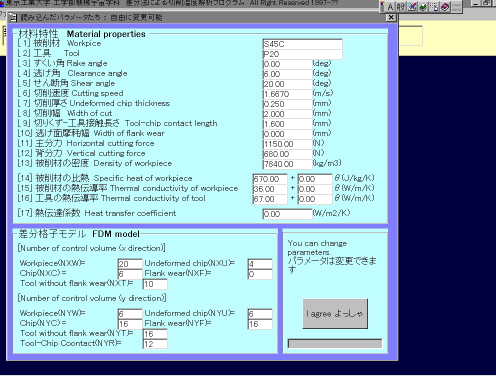
Input Data
At first step you must open the input data file.
The tool geometry, cutting conditions, cutting forces and thermal properties
have to be written in this data file.
Ofcourse, you can change each data in this dialogue.
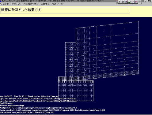
FDM Mesh
When the input datas are satisfied, the FDM mesh is shown.
You can also change the mesh by changing the input data file.
Calculation Process Dialogue
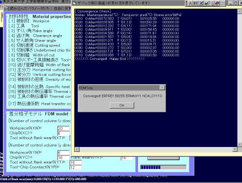
When the input datas are satisfied, the calcluation starts.
The calculation will repeat until the results are converged.
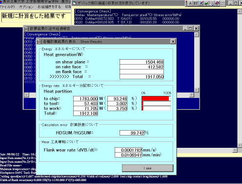
Energy Ratio Dialogue
When the calculation finishes, the energy distribution ratio is shown.
In short, the degree for the tool and for the workpiece.
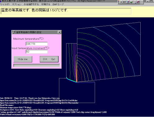
View temperature distribution with contour lines
The contour line can be shown.
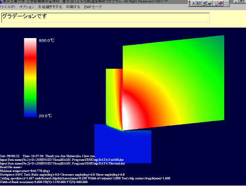
View temperature distribution with gradation colors
Beautiful 256 colors gradation can be shown.
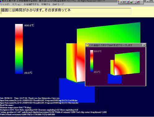
Save BMP Image
The mesh, contour line and gradation representation can be printed out
by Windows API (printer function).
And more over, these figure can be saved as BMP files.
This function is very usuful.


